What is coupling and instance?

In a normal feeling, a coupling is a product or system employed to join two different objects or factors with each other. Couplings are generally applied in numerous fields, such as mechanics, engineering, and electrical units, to be a part of or link diverse elements.

Listed here are a number of examples of couplings:

1. Mechanical Couplings: Mechanical couplings are used to join two rotating shafts in equipment and machines. Some widespread examples include:

a. Sleeve or Muff Coupling: This kind of coupling is made up of a hollow cylindrical sleeve that matches more than the ends of two shafts, with keys or splines furnishing a safe relationship.

b. Clamp or Split Coupling: Clamp couplings have two halves that are tightened close to the shaft ends using bolts or clamps, making a rigid relationship.

c. Equipment China coupling: Equipment couplings use interlocking tooth on the coupling halves to transmit torque while allowing for for a specified volume of misalignment.

two. Electrical Couplings: Electrical couplings are employed to join and transmit electrical indicators between different factors or units. Examples involve:

a. Wire Connectors: Wire connectors, such as twist-on wire nuts or China coupling crimp connectors, are utilized to sign up for electrical wires securely.

b. Plug and Socket Connectors: These couplings consist of male and feminine connectors that help the relationship and disconnection of electrical units, this sort of as ability cords or audio cables.

c. Terminal Blocks: Terminal blocks give a practical way to link multiple wires or electrical conductors in a manage panel or junction box.

three. Fluid Couplings: Fluid couplings use hydraulic concepts to transmit energy amongst two factors. Examples include:

a. Hydraulic Couplings: Hydraulic couplings, these types of as speedy-disconnect couplings, enable for simple and secure relationship and disconnection of hydraulic traces.

b. Pneumatic Couplings: Pneumatic couplings are used to hook up and disconnect air provide strains in pneumatic techniques, these as in air compressors or pneumatic applications.

four. Optical Couplings: Optical couplings are made use of in optical systems to join or align optical fibers or factors. Examples consist of:

a. Fiber Optic Couplers: Fiber optic couplers help the relationship of optical fibers, enabling alerts to be transmitted in between them.

b. Lens Couplings: Lens couplings are made use of to align and hook up lenses in optical devices, ensuring correct target and mild transmission.

These examples illustrate the diverse selection of couplings and their programs throughout diverse fields. Couplings engage in a critical job in connecting and China coupling supplier integrating several components, enabling the effective transmission of energy, signals, or fluids in between them.

can an injection molding section have larger thickness?

Certainly, an injection molded section can have better thickness in certain parts. The crucial is to preserve uniform wall thickness the place probable, but there are situations the place varying wall thickness is essential or advantageous. Listed here are a handful of eventualities exactly where greater thickness may be utilised:

1. Structural Specifications: Specified locations of a aspect may possibly require higher thickness to provide the required structural integrity and energy. This is frequent in load-bearing or higher-worry regions exactly where additional material is wanted to endure used forces.

2. Reinforcement: Larger thickness can be utilized to enhance distinct sections of the element. This can be attained through the addition of ribs, gussets, or other structural components that enhance stiffness and cut down deflection or deformation.

three. Inserts or Steel Inserts: If the component requires metal inserts or threaded inserts for assembly or reinforcement, it really is popular to layout thicker regions to accommodate the inserts securely. The extra materials thickness delivers the vital energy and security for the inserts.

four. Heat Sink or Thermal Management: In apps where by heat dissipation is vital, thicker sections can be used as heat sinks or to accommodate further cooling attributes these types of as fins or channels. Enhanced material thickness will help to take up and dissipate warmth proficiently.

5. Aesthetic Things to consider: In some scenarios, increased thickness may well be deliberately included for beauty uses. This can build a desired visual effect, give a additional sizeable or sturdy look, or support obtain distinct style and design aesthetics.

While it is achievable to have different wall thickness in an China Injection molded parts supplier molded element, it can be important to think about the implications on mold design and style, content flow, cooling, and portion warpage. Right investigation and optimization, which includes the use of mildew movement simulation software, can assistance assure that the element can be successfully produced with the desired wall thickness versions although reducing prospective molding troubles. Collaboration with skilled mildew designers and producers is highly recommended to tackle any worries associated with various wall thickness.

what is a gearbox?

A gearbox, gearbox factory also recognized as a equipment reducer or equipment transmission, is a mechanical product that is employed to transmit electricity and torque from a power source (these as an engine or motor) to a driven system or load. It is made up of a established of gears arranged in a particular configuration to realize the preferred speed reduction or torque multiplication.

The primary purpose of a gearbox is to modify the speed and torque attributes of the enter electric power source to match the needs of the pushed system or load. By choosing distinct equipment ratios, a gearbox factory can maximize torque when decreasing velocity (for increased torque programs) or maximize pace whilst decreasing torque (for greater velocity apps).

Gearboxes can be observed in a vast vary of applications, like vehicles, industrial machinery, robotics, wind turbines, and a lot of other folks. They engage in a essential role in optimizing the efficiency and effectiveness of mechanical units by providing the vital energy and management in excess of rotational pace and torque.

how to attach rhode equipment bike rack?

Attaching a Rhode Gear bicycle rack usually entails securing it to the rear of your vehicle. Here’s a basic information on how to connect a Rhode Equipment bicycle rack:

Be aware: The distinct directions may well range depending on the model of your Rhode China gear rack distributor bicycle rack. It really is critical to talk to the rack’s instruction manual for thorough guidance and any distinct prerequisites.

Tools Desired:

– Rhode Equipment bicycle rack

– Adjustable wrench or Allen wrench (if necessary)

– Rubber straps or bungee cords (if incorporated)

Guidance:

1. Preparation:

– Assure that your vehicle is parked on a degree area and the parking brake is engaged.

– If you have a hitch-mounted bicycle rack, make certain that your automobile has a hitch receiver mounted. The hitch receiver really should match the dimensions and class specified by the bike rack’s guidance.

2. Place the bike rack:

– Placement the bicycle rack close to the rear of your car, aligning it with the hitch receiver or trunk area. Make certain that the rack is centered and degree.

3. Hitch-mounted bike rack:

– If you have a hitch-mounted bike rack, China gear rack distributor slide the shank of the rack into the hitch receiver. Align the holes on the shank with the hitch pin holes.

– Insert the hitch pin or bolt by the holes and secure it tightly. Some racks could have to have the use of a wrench or Allen wrench to tighten a bolt.

– Use any locking mechanisms or anti-rattle equipment presented with the rack to protected it more and minimize movement while driving.

four. Trunk-mounted bike rack:

– If you have a trunk-mounted bike rack, China gear rack manufacturer placement the rack on the trunk or rear hatch of your motor vehicle in accordance to the manufacturer’s guidelines.

– Ensure that the rack is secure and stable on the trunk or hatch. Some trunk-mounted racks use straps or hooks that attach to the edges of the trunk or hatch.

– Connect the straps or hooks to the correct locations, making certain a tight and protected fit. Abide by the manufacturer’s directions on how to thoroughly safe the rack to your certain car or truck.

five. Safe the bikes:

– At the time the bike rack is securely attached, diligently location your bikes onto the rack.

– Connect the bike frames to the selected mounting factors on the rack. Most racks have adjustable straps or clamps that secure the bike frames in location.

– Make confident the bikes are evenly dispersed and appropriately secured to stop any movement or hurt in the course of transportation.

six. Validate steadiness:

– Following loading the bikes, gently shake the rack and bikes to make sure they are steady and correctly secured. Look at that there is no abnormal motion or wobbling.

– If vital, use further rubber straps or bungee cords (if incorporated with the rack) to further secure the bikes and stop them from shifting throughout transit.

Often ensure that the bike rack and bikes do not hinder your rear lights, license plate, or visibility whilst driving. On top of that, it is really significant to abide by any more guidance or recommendations provided by Rhode Gear for your precise model of bike rack.

Can helical gears be perpendicular?

No, helical gears are not able to be perpendicular to every single other. Helical gears are created to have angled teeth that are slice in a helical condition. The helix angle decides the course and angle of the tooth, permitting them to have interaction efficiently and transmit power involving parallel or intersecting shafts. The helix angle guarantees appropriate meshing and efficient electrical power transmission by giving a gradual get hold of involving the gear teeth.

If the China helical reducer exporter gears have been to be positioned perpendicular to just about every other, the enamel would not be equipped to mesh effectively, ensuing in weak call, inefficient electricity transmission, China helical reducer supplier and improved don. Perpendicular placement of helical gears would induce the teeth to clash and interfere with every single other, major to prospective problems to the gears and the equipment system as a complete.

To transmit movement amongst perpendicular shafts, other types of gears, such as bevel gears or worm gears, are typically applied. These gear kinds are specially created for perpendicular shaft preparations and present effective electric power transmission in these kinds of configurations.

What is the distinction among harmonic and cycloidal gearbox?

Harmonic and cycloidal gearboxes are each varieties of equipment techniques that offer speed reduction and torque multiplication. Even so, they work primarily based on various principles and have distinct traits. Listed here are the essential discrepancies amongst harmonic and cycloidal gearboxes:

Functioning Basic principle:

– Harmonic Gearbox: A harmonic gearbox, also known as a strain wave gearbox, operates primarily based on the principle of flex spline and wave generator. It consists of a adaptable spline (flex spline), a rigid outer spline (round spline), and an elliptical or wave-shaped ingredient (wave generator). The movement of the wave generator produces a deformity in the flex spline, resulting in a relative motion involving the flex spline and circular spline, which provides the velocity reduction and China cycloidal gearbox distributor torque multiplication.

– Cycloidal Gearbox: A cycloidal gearbox, also identified as a cycloidal travel or cycloidal reducer, operates centered on the principle of the cycloidal motion. It is composed of an input shaft, eccentric pins or cams, a cycloidal disc, and an output shaft. The eccentric pins or cams, when rotated, induce the cycloidal disc to transfer in a cycloidal motion, ensuing in output rotation. The numerous points of call involving the pins or cams and the cycloidal disc permit torque transmission and velocity reduction.

Equipment Layout:

– Harmonic Gearbox: Harmonic gearboxes generally have a compact design and style and contain an elliptical wave generator that deforms the flex spline to generate the desired motion. They typically have a large equipment reduction ratio and exhibit higher precision and reduced backlash. Harmonic gearboxes are frequently utilised in programs where by superior precision and compact measurement are vital, such as robotics and aerospace.

– Cycloidal Gearbox: Cycloidal gearboxes have a distinctive structure with eccentric pins or cams and a cycloidal disc. The pins or cams generate a cycloidal movement in the disc, resulting in output rotation. Cycloidal gearboxes provide high torque potential, compact sizing, and easy movement command. They are usually utilized in purposes that involve superior torque and precise movement manage, this sort of as robotics, industrial machinery, and automotive programs.

Strengths and Disadvantages:

– Harmonic Gearbox: Harmonic gearboxes offer you superior precision, lower backlash, and compact measurement. They supply excellent motion management, repeatability, and accuracy. However, they can be more highly-priced and have restrictions in terms of torque capacity and longevity.

– Cycloidal Gearbox: China cycloidal gearbox gearboxes deliver high torque potential, China cycloidal gearbox compact measurement, and smooth movement regulate. They are recognized for their longevity and potential to tackle shock masses. Nonetheless, they may well have a little higher backlash as opposed to harmonic gearboxes, and their structure could be more sophisticated.

In summary, harmonic and cycloidal gearboxes have different running ideas, equipment styles, and traits. Harmonic gearboxes excel in precision and compactness, while cycloidal gearboxes present superior torque capacity and toughness. The option in between them depends on the specific necessities of the application, this kind of as precision, torque capability, compactness, and cost considerations.

how does a rack and pinion equipment do the job?

A rack and pinion equipment process is a variety of mechanical unit applied to transform rotational movement into linear movement. It consists of a straight toothed rack (a flat bar with tooth alongside its size) and a pinion equipment (a compact gear with teeth). Here is how the rack and pinion equipment performs:

one. Rack: The rack is a straight bar with evenly spaced tooth together its duration. It acts as a linear gear and delivers a straight route for movement. The tooth on the rack mesh with the tooth on the pinion equipment.

two. Pinion Gear: The pinion equipment is a tiny equipment with enamel that mesh with the enamel on the rack. It is typically connected to a rotary enter, these as a steering wheel in the case of a car’s steering procedure. The pinion equipment rotates when the enter is turned.

three. Meshing of Tooth: As the pinion equipment rotates, its tooth engage with the tooth on the rack, causing the rack to go linearly in response to the rotation of the pinion China gear rack distributor. The rotation of the pinion equipment converts into linear motion of the rack.

four. Course of Motion: The route of linear movement of the rack relies upon on the orientation of the pinion equipment. If the pinion gear is oriented vertically, the rack will move up and down. If the pinion equipment is oriented horizontally, the rack will shift left and right.

5. Mechanical Advantage: The rack and pinion gear procedure is made to give mechanical edge. For the reason that the pinion equipment is smaller sized than the rack, just about every rotation of the pinion equipment final results in a better linear displacement of the rack. This delivers a mechanical advantage, allowing for China gear rack supplier for precise and effective motion conversion.

Applications of Rack and Pinion Equipment:

– Steering process in cars: Rack and pinion gears are commonly employed in the steering programs of cars and trucks, gear rack factory trucks, and other motor vehicles. When the driver turns the steering wheel, it rotates the pinion gear, which moves the rack, thus steering the wheels.

– Linear actuators: Rack and pinion gears are utilized in several linear motion programs, such as in industrial equipment and automation units. The rotational input is utilised to produce linear motion for responsibilities like opening and closing doorways, moving platforms, or managing robotic arms.

The simplicity and efficiency of rack and pinion equipment devices make them extensively used in several mechanical purposes exactly where converting rotational motion into linear movement is required.

What is the theory of coupling?

The principle of coupling, in the context of mechanical methods, refers to the thought of connecting two shafts or factors with each other to transmit ability and torque. The coupling factory serves as a link concerning the driving shaft (input) and the driven shaft (output), making it possible for the transfer of rotational movement and China coupling manufacturer torque from just one component to yet another.

The key principle driving coupling is to build a trusted and successful connection amongst the shafts whilst accommodating certain variables, these as misalignment, adaptability, shock absorption, and vibration isolation. Couplings are designed to deal with these requirements and be certain sleek ability transmission though minimizing anxiety, dress in, and opportunity injury to the connected elements.
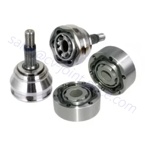
The distinct rules of coupling can differ depending on the form of coupling getting used. For case in point:

one. Adaptable Couplings: The basic principle of versatile couplings will involve supplying a certain degree of adaptability to compensate for misalignment amongst shafts. Flexible couplings normally integrate features these as elastomeric inserts, equipment teeth, or common joints, which allow for angular, parallel, or axial misalignment though transmitting torque.

two. Rigid Couplings: Rigid couplings aim to make a reliable and rigid connection concerning shafts, making certain precise torque transmission devoid of any adaptability. The theory below is to sustain specific alignment amongst the shafts via a limited match, keyway, or flanged link.

3. Fluid Couplings: coupling factory Fluid couplings operate on the basic principle of hydraulic transmission. They use a fluid medium, normally oil or a equivalent substance, to transmit torque concerning the input and output shafts. The theory entails the utilization of the impeller and turbine, which generate fluid stream and correctly transmit torque.

No matter of the unique variety of coupling, the overall theory is to set up a link that enables for the productive transfer of electric power and torque when addressing the prerequisites of the distinct software, such as misalignment compensation, shock absorption, flexibility, or vibration isolation. By adhering to these principles, couplings ensure smooth and dependable procedure of mechanical techniques.

What are the signs or symptoms of a lousy CV joint?

A poor CV joint (Continual Velocity joint) can show different signs and symptoms, indicating opportunity concerns with the joint or its linked parts. Below are some prevalent indicators of a failing CV joint:

one. Clicking or popping noises: Just one of the most visible symptoms of a lousy CV joint is a clicking or popping seem when creating sharp turns, particularly through acceleration or deceleration. This sound is frequently extra pronounced when the joint is under load, these kinds of as when maneuvering or driving in tight corners.

two. Vibrations or shuddering: A failing CV joint may possibly lead to vibrations or shuddering sensations in the automobile, specifically in the course of acceleration. The vibrations can array from moderate to extreme and may possibly be felt in the steering wheel, floorboards, or even all over the entire automobile.

three. Grease leakage: CV joints are ordinarily packed with grease to lubricate the joint and China cv joint distributor lower friction. If the CV joint’s protecting boot (rubber or plastic covering) turns into damaged, torn, or cracked, it can make it possible for China cv joint manufacturer the grease to leak out. Inspect the interior and outer China cv joint distributor joint boots for symptoms of grease leakage or harm.

four. Axle grease on wheels or beneath the car or truck: If a CV joint boot is broken and grease leaks out, you might recognize axle grease splattered on the interior edge of the wheels or on the underside of the vehicle. It can appear as a thick, dark or light-coloured substance.

5. Constrained maneuverability or trouble turning: A compromised CV joint can consequence in limited maneuverability or issues turning the vehicle, China cv joint manufacturer primarily when undertaking sharp turns or navigating corners. The steering may perhaps truly feel rigid or unresponsive.

6. Uneven tire use: A failing CV joint can lead to uneven tire dress in, particularly on the afflicted wheel. The excessive vibrations or irregular movement induced by a harmed CV joint can direct to uneven wear styles on the tire tread.

If you suspect a dilemma with your CV joints centered on these signs, it is advisable to have your auto inspected and fixed by a capable mechanic or automotive technician. They can evaluate the condition of the CV joints, carry out any vital repairs or replacements, and guarantee the risk-free and ideal procedure of your automobile.

how does a gearbox do the job in a car or truck?

In a auto, the gearbox, also regarded as the transmission, plays a very important function in transmitting electricity from the engine to the wheels whilst enabling the driver to manage the vehicle’s velocity and torque. The gearbox is effective in conjunction with the engine and the drivetrain to improve performance and give different equipment ratios for different driving problems. This is a simplified clarification of how a gearbox will work in a vehicle:

1. Input from the Motor: The gearbox gets rotational electric power, or torque, from the engine by the enter shaft. The engine’s crankshaft is linked to the gearbox’s enter shaft.

2. Gear Choice: The driver selects the desired equipment employing the gear selector, normally found on the centre console or the steering column. The gear selector enables the driver to choose involving solutions these kinds of as Park (P), Reverse (R), Neutral (N), Push (D), and China gearbox distributor several numbered gears (1, two, 3, and many others.).

three. Gear Ratios: Every single equipment in the gearbox has a particular equipment ratio, which decides the connection involving the speed of the engine and the rotational velocity (RPM) of the wheels. Decreased gears supply larger torque multiplication for setting up and climbing, although better gears provide larger speed at decrease engine RPM for cruising.

4. Output to the Drivetrain: The output shaft of the gearbox is connected to the drivetrain, which transfers electric power to the wheels. The drivetrain usually involves components this sort of as driveshafts, differentials, and axle shafts that distribute electric power to the wheels.

five. Shifting Gears: When the driver modifications gears, the gearbox engages a particular gear ratio by connecting distinctive sets of gears inside the transmission. This is generally attained making use of synchronizers and shifting forks to match the rotational speeds of the gears before participating them.

6. Clutch (Guide Transmission): In a manual transmission car, a clutch is used to temporarily disconnect the engine’s ability from the gearbox through gear variations. The driver operates the clutch pedal to disengage the clutch, permitting easy equipment shifts.

7. Automated Transmission: In an computerized transmission car or truck, the China gearbox distributor automatically selects the suitable equipment centered on components these as car or truck velocity, engine load, China gearbox exporter and driver enter. Computerized transmissions use a torque converter or twin-clutch technique to effortlessly transfer energy from the motor to the transmission without the need of the require for a clutch pedal.

By deciding upon various gears, the gearbox will allow the motor to operate proficiently inside its exceptional RPM variety when delivering the essential torque and velocity for a variety of driving situations. This makes it possible for the driver to manage the car’s acceleration, pace, and overall performance centered on their needs and the street circumstances.